Design and Construction for Sanitary Fluid Processing Equipment-3
Sanitary Construction and Installation
Besides the designing requirements on materials and contact surfaces, sanitary fluid processing equipment should also allow for easy cleaning and inspection. All the contact surfaces should be free of sharp corners and crevices to avoid potential hold up of materials or solutions. The whole system should comply with the cleaning-in-place (C.I.P.) standard for interior surfaces cleaning without disassembly.
A. Internal Angles
Internal angles should be coved or rounded with defined radius as shown in Picture 1. Equipment standards specify appropriate radius for specific equipment applications and components. For example, radius requirements stated in the 3A Sanitary Standards indicate that all internal angles of 135 degrees or less should have radius of 0.25 inch minimum, except for cases of functions within certain specifications.
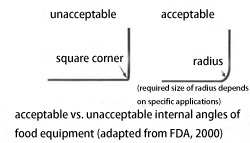
Pic.1
B. Permanent Joints
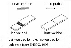
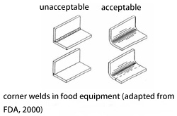
All joints should be smooth, durable and meet all sanitary design criteria. Sanitary equipment standards generally require that welded joints on stainless steel surfaces be continuous, butt-type joints (See Picture 2) and ground to at least as smooth as a No. 4 finish. If the welded joint is at a corner, it must be coved to the appropriate radius and ground smooth (see Picture 3). Press fits and shrink fits are generally discouraged and should be limited only to applications where welded joints are not possible (e.g. bushings).
 |
|
|
Pic.2 |
Pic.3 |
C. Non-Product Contact Surfaces
Non-product contact surfaces of sanitary fluid processing equipment are a well documented source for environmental contamination of pathogens (especially Listeria monocytogenes). They can also be the potential harborage areas for insects and rodents. Therefore, it's a must to ensure that these surfaces are designed to be without any sanitary defect or shortage.
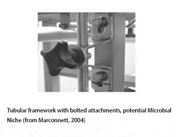
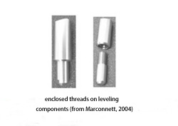
- To avoid niches for microbiological growth, tubular steel equipment framework should be entirely sealed and not penetrated (e.g., bolts, studs, see Picture 4). Threads used on leveling components should be of the enclosed type as shown in Picture 5. Whenever practicable, attachments should be welded to the tubing surface instead of via drilled and tapped holes.
- Ledges or areas where dust can collect should be avoided. Equipment tops, shields, covers or boxes should slop at a 45 degree angle or more.
 |
 |
| Pic.4 | Pic.5 |
D. Sanitary Equipment Installation
Sanitary fluid processing equipment should be installed in a logical sequence to avoid cross contamination. Spaces around equipment, inter-equipment or between equipment and walls should be adequate enough to allow for sufficient cleaning. There should be no potential harborages for insects and rodents. Unless sealed to walls, sanitary equipment should be located at least 4 inches away from the walls. Floor mounted equipment should be sealed to the floor, platform or pedestal or should be no less than 6 inches from the floor. Table mounted equipment should be sealed to the table, or be no less than 4 inches from the counter top (see Picture 6).

Pic.6
Prev: C.I.P. Technology and Systems, Operation and Advantages Next: Design and Construction for Sanitary Fluid Processing Equipment-2